This is part 3 of "building an audio mixer with effects". For part 1 go here, and for part 2, go here.
The mixer is working fine, and already has got two PT2399 circuits for delay. But now it is time to add some reverb. For reverb I decided to use an FV-1 based design. Experimental Noize has some nice small boards built around this chip, preprogrammed for different purposes. I decided to go for the SKRM-C8-R02 Mono-In/Stereo Out reverb and delay module.
I wanted to use a rotary switch to select between the different programs. The SKRM data sheet proposes to use a 74HC148 8 to 3 Line Priority Encoder for this purpose. Hence, there is a need for a small PCB to mount the SKRM and the 74HC148 (in addition to some additional components). Although I have used KiCad and OSH Park for PCB production previously, I wanted to test Fritzing for this small project.
I drew a quick diagram in Fritzing, swithced to PCB-view and the auto-router took care of the rest (at least most of it).
After a about ten days the card arrived in my mailbox.
The board came out quite nicely. Although I am very satisfied with the result, I do not think I will use Fritzing for my next project. OSH Park and other alternatives are way cheaper, and I think the Fritzing software is a bit limited compared to Eagle or KiCad (and even if the Fritzing-software is very simple to use, Eagle and KiCad are not that difficult to learn). The files are available at the Fritzing-site in case you are interested.
It took about 10 minutes to add the few components :-). It is only a 74HC148, a capacitor and a pull up resistor network.
Then I slammed the SKRM on top of it, soldered the connectors, and started jamming with some heavy reverb. But wait, I forgot one thing, namely to securely mount the PCB inside the mixer. A simple solution is to screw standoffs to the front panel, but the screws would interfere with the front panel design. I could also glue the standoffs to the front panel, but I just hate to glue things together when there is a slight chance that I might want to dismantle it later.
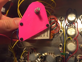
Hence, I created a plate to screw the PCB standoffs to, that is fastened with the rotary switch. It is designed in OpenSCAD and 3D-printed.
The above picture show how it looks like inside the mixer. Notice that the plate (in pink) is fastened together with the rotary switch.
The above picture show how the mixer looks like inside. The SKRM is driven by a LM7805 which is connected to the +12V rail (the blue heatsink can be seen on the bottom part of the picture). The circuit draws about 170mA, even if the data sheet states it should be less than 75mA. The reason? I do not know.
DIYcrap mixer. Now with reverb.


No comments:
Post a Comment