Showing posts with label Homebrew. Show all posts

Monday, December 26, 2016

Homebrew 40dB step attenuator

A home lab needs a step attenuator.  It helps in evaluating RF amplifiers, filters and receivers. Both the legendary EMRFD-book, the ARRL handbook, and a variety of QST-articles provides circuit examples for building a homebrew device. Most of them follow the design principles from the January 1967 edition of the 73 magazine (all editions can be found for free online).


I built my device base on the 73-magazine article, but choose 20 dB, 10 dB, 5 dB, 3 dB and 2 dB sections, giving 40 dB in total. The choice was basically based on the need for about 40 dB total, and the physical limitations in the aluminum box at hand giving room for only 5 pad sections.


Each pad is a basic 50-ohm in/out pi-network. I used slightly different values from those in the article. I used standard DPDT switches (from Tayda) and attempted to shield the sections using double sided copper clad boards.


Before presenting my own result, lets examine the results from the now fifty year old 73-article (congrats).


Using shielding, the authors (W6AIG and WA6RDZ) obtained almost flat response up to about 100 MHz for both the 3, 6, 10 and 20 dB pads. The 450 MHz results seem to be off by about 2 dB for each pad. The unshielded version (albeit the 20 dB section was shielded) is off by about 5 dB at 450 MHz. Lets look at my version, built 50 years later (with much less experience that is).


Above is the plot with all sections OFF from 1 Mhz to 400 MHz. The curve is reasonable flat, and maxes at 247 MHz with -1.47 dB.


Above is the 2 dB section over the same frecquency range. The response is close to 2 dB within the HF spectrum but -3.57dB at 247 MHz.


The 3 dB section above. Almost the same results. -5 dB at 292 MHz.


The 5 dB section. Can be defined as 5 dB within the HF spectrum but goes down to -7.43 at about 400 MHz.


The 10 dB section is better. Pretty close to 10 dB over the measured range. In fact, the 10 dB pad was fairly ok up to 1.5 GHz when used alone.
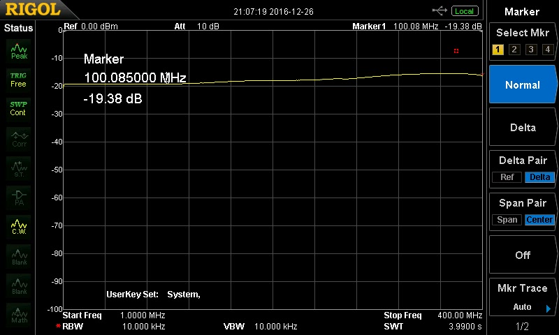

The 20 dB section is the worst. Most articles recommends no more than 20 dB attenuation per section in a step attenuator as there will be some leakage. My 20 dB section goes up to only 15 dB at 375 MHz but is still close to 20 at 100 MHz.


All sections swithed to ON. Should yield 40 dB over the range, but goes down to 30 dB at 400 MHz. This proves that the step attenuator is of little use in the entire VHF range, but could be useful up to 100 MHz. Lets look at the HF range only (1-30 MHz).


All attenuator sections is switched ON, which gives the worst results. Still, it is close t 38-39 dB over the HF range.

I am satisfied with these results since I am only going to use the device below 50 MHz. However, I am a bit disappointed that I was not able to get the same results as the authors of the fifty year 73-article. I was pretty close at 100 MHz but no cigar... My attempts to shield the 20 dB section with more copper clad boards did not give impressive results (only 0.5 dB better, at best), so those were left out in the final device. It could be that other switches could give better results. Your mileage (or attenuation) may vary.


Monday, December 19, 2016

Homebrew return loss bridge

I have had some problems making return loss measurements using my homebrew directional coupler, and decided to build the return loss bridge from EMRFD and the ARRL handbook.


This is the final device. Obviously, "IN" denotes RF input, "DUT" denotes Device Under Test, and "DET" means Detector.


The circuit (picture from the handbook) is fairly simple. I used 51 Ohm resistors and a FT 37-43 with 10 bifilar turns and BNC connectors.


 I connected the bridge to a spectrum analyzer to get a picture on the directivity.


I used my homebrew dummy load as a 50 ohm terminator.


I guess you need experience with a similar spectrum analyzer to understand the plot, but anyways, I measured a maximum return loss of 37.6 dB, which I believe is fairly good directivity for a homebrew return loss bridge. It should be noted that the dummy load is not an excellent terminator, but is ok up to about 100 MHz.


The same plot show the return loss on my shortened 20 m dipole. The SWR is at its best at 1.46 at 13.8 MHz. It seem a bit detuned as it should resonate in the low end of the 20 m band, but fixing the antenna is another project.

All in all, the return loss bridge was a fun project, and I am sure it will be a useful tool for future measurements in my little home lab.


Sunday, August 14, 2016

Dekatron tubes controlled by arduino

Interfacing dekatron tubes with a microcontroller is fairly easy, once you understand how the tubes work. Threeneuron's Pile o'Poo of Obsolete Crap provides the necessary background information and schematics for making this work.


I used two russian OG-4 tubes. I prefer the orange look of the neon tubes rather than the purple look of the argon filled OG-3 tubes. The latter tubes just look to modern for my liking. On the above picture you can see how I have mounted the tubes on a rig alongside two Magic eye tubes.


The schematics is more or less directly from the Threeneurons page. It uses two output pins from the arduino, and one input-pin. My high voltage supply is somewhat unstable, so I used a zener diode to protect the input pin from over voltage.


The above picture show the PCB, soldered Manhattan style. The high voltage power supply is from Ebay, and works best with less than 10V on the input side, but can provide up to 1000V. The current is however in the microampere area, hardly enough to kill a mosquito, and just enough to drive two dekatrons at 450 V. There is also some other outputs on the board providing around 170 and 250 V respectively.


I am going to use the dekatrons as part of the display solution for my homebrew RF transceiver. Now I have the Nixie display, magic eyes and the dekatrons under control (the radio itself is not finished yet). Even my cardboard mock-up is looking great!


The above video show the prototype assembly.

The dekatron code is as simple as this. Notice that the input pin is not used in the below code.

int DekIn1=13;
int DekOut11=12;
int DekOut12=11;
int DekIn2=6;
int DekOut21=5;
int DekOut22=4;

int count=0;

void setup()
{
  pinMode(DekOut11, OUTPUT);      // sets the digital pin as output
  pinMode(DekOut12, OUTPUT);      // sets the digital pin as output
  pinMode(DekOut21, OUTPUT);      // sets the digital pin as output
  pinMode(DekOut22, OUTPUT);      // sets the digital pin as output
}

void loop()
{
  if(count<30)
  {
    digitalWrite(DekOut11, HIGH);
    delay(10);   
    digitalWrite(DekOut21, HIGH);
    delay(50);                 
    digitalWrite(DekOut12, HIGH);   
    digitalWrite(DekOut22, HIGH);
    delay(10);  
    digitalWrite(DekOut11, LOW);  
    digitalWrite(DekOut21, LOW); 
    delay(10);  
    digitalWrite(DekOut12, LOW); 
    digitalWrite(DekOut22, LOW); 
    delay(10);
    count++;
  }
  else if(count>=30 && count < 60)
  {
    digitalWrite(DekOut12, HIGH);
    digitalWrite(DekOut21, HIGH);     
    delay(10);                 
    digitalWrite(DekOut11, HIGH); 
    digitalWrite(DekOut22, HIGH);    
    delay(5);  
    digitalWrite(DekOut12, LOW); 
    digitalWrite(DekOut21, LOW);       
    delay(5);  
    digitalWrite(DekOut11, LOW); 
    digitalWrite(DekOut22, LOW);  
    delay(5);
    count++;
  }
  else
    count=0;
  
  
}

Thursday, May 5, 2016

EMRFD Direct conversion 40m receiver in a tea caddy

I woke up one day eager to build something simple (at least I thought is was simple) and opened up the first chapter in EMRFD and decided to build the 40m direct conversion receiver. I already had most of the components in my junk box. By the way, Experimental Method in RF Design (EMRFD) is the best book about homebrewing amateur radio gear. You should get it if you don`t have it.

I know you are sitting on the edge of your chair, eager to see the end result, so I will give it to you straight away.  Here it is: My 40m Direct Conversion Tea Caddy Receiver.


Then, lets rewind back to the build process. I started off with the schematics from EMRFD.

The first chapter of EMRFD is available online, so I guess I will not go to jail by showing the circuit diagram here. 
The receiver is based on a NE602 gilbert cell mixer and the famous and old LM386 audio amplifier. The rest of the components are a few capacitors, including three tunable, two T37-6 toroids, and some resistors. 


Prototype of the mixer circuit almost done.


Prototype of the receiver is now finished. In the first version I followed the circuit diagram from EMRFD 100% and used two 75pF air tuning caps (from Russia). The receiver was very difficult to tune with those caps, and I got some oscillations. It was a very fine Theremin, however.


The above video show the performance of the receiver. It is not very sensitive, but it is working. In this version I had some problems with the preselector filter. It seemed like all the RF went straight to ground. Trying to debug this problem did not help much, so in the above video, the antenna is connected straight to the NE602.


For the second version I used just one tuning capacitor of 80pF. It was even more difficult to tune, but I got rid of the oscillations. In addition, I went ahead and used a different preselector circuit from QRPme.com Sudden receiver.


On the final version, I used a 60pF polyvaricon with a reduction drive as the tuning cap and adjusted the oscillator circuit to enable the receiver to tune from 6.9-7.3MHz. It was build using Qrpme MePads in sort of Manhattan style. I soldered the component on two PCB boards which was soldered together to fit in a oriental Chinese tea caddy.


Finally, I added a switch and a 5mm LED. The receiver is powered by 6xAA batteries. It could probably run on anything between 6-9 volts. In the datasheet of the NE602, it says that the maximum supply voltage is 9V, so I am probably pushing it a bit. I used a protective diode and a series resistor for safety reasons and to keep the voltage down a bit.


I used an SMA-connector on the back.


The final receiver. Eager to sniff RF from the ether...


The schematics for the receiver (using Fieldnotes schematics software). The series diode is not in the schematics, but I put it in for good measures. I used somewhat different component values in the colpitts oscillator than those in EMRFD.

The verdict

It was a very fun build. It is a simple circuit on the paper, but it sure teaches you a lot regarding radio functionality. Alright, the receiver works, but it does not seem very sensitive. I should be noted, firstly: that I do not have any 40m capable receiver to compare with. Secondly, my antenna is not very good on 40m. Thirdly, I have no idea what I am doing.


That being said: CW pops in very nicely, while SSB is a bit difficult to tune in. The oscillator seem suprisingly stable given that it is a VFO rather than a VXO, and the fact that I used random capacitors and no fancy NP0-ones. At least it was stable enough to receive RTTY with fldigi during a brief experiment.

In a future version I would like to add some sort of audio filtering before the LM386. Some sort of audio gain control would also be nice, since it is a bit loud on my iPhone headphones on strong signals. 

Further reading:


Saturday, December 5, 2015

Homebrew SWR and power meter

First of all, this SWR meter in this article is not exactly homebrew, as I based the circuit on the schematic in the excellent book Arduino Projects of Amateur Radio. Although I bought the book and respect the copyright of the authors I will share my own schematic here. Why? First, the design in the book is not completely original and is based on similar designs from others. One example here.  Second, I changed a few things, removed some stuff,  and added some other things, to my own liking, so the design is not identical anymore.


The circuit is based on two AD8307 log amplifiers, which are connected to the forward and reflected ports on a directional coupler.  The AD8307 amplifiers gives a DC voltage of about 25mV/dB of the input signal, which is amplified using an opamp (LM324). The opamp also provides the reference voltage to the Arduino (AREF) to ensure that the full ranges of the A/D converters are used.


I used the fourth opamp in the quad LM324 to provide input voltage reading. That is why the PCB in the picture has two power jacks. One input and one output. That way I know the drive voltage for the radio. I primary plan to use this device for my Softrock.


I created the schematic and the board in Eagle, and submitted the gerbers to Elecrow. I received 10 PCBs after about 25 days.


The board is not much larger than a standard 20x4 LCD.


I choose to use an Arduino nano rather than populating a AVR328 on the board and messing with USB converters. I am glad I did. I did one mistake on the board however. The Arduino was not powered from the 5V rail. The problem was that it was an error on the Eagle footprint for the Arduino Nano. I just downloaded the footprint file uncritically from the Internet without checking it. Other than that, It was fine.


Another problem was that I got oscillations on the LM324 opamps connected to the AD8307. The oscillations were around 40KHz and about 400mVpp on top of the DC signal. Hence it was impossible to calibrate the device. The solution was to desolder the output capacitors on the LM324. I do not think they are really needed on a DC design.


This was my first SMT design, and I am fairly happy with the result. The SWR and the power measurements seems accurate. I used the Arduino software from the book, and modified it to include a larger display and some other things. As you may notice, there are no buttons on the device. Originally I planned to use a rotary encoder and a bunch of menus, but as they say in the Soldersmoke podcast, menus are for restaurants. I totally agree. Besides, programming all kinds of features to the device is totally insane. This is a simple SWR meter and thats it. 

The files are available here, should you be interested. Note that there is an error in the schematic. The Arduino is missing +5V, but it should be easy to fix.

Sunday, September 13, 2015

Directional coupler

Introduction


I have been struggling to understand how my simple dipole antenna works (or doesn't work). The diycrap way to understand stuff is usually to read, build and measure, and then read some more. The key factor here is the measuring part, as I need to measure the standing wave ratio (SWR) on the feed line, as this is a key parameter. To measure the SWR, I need a directional coupler. And it is going to be homebrew.

Later, the coupler is going to be the basis of a SWR-meter, but for now, lets just look at the coupler.


The directional coupler design is classic and well known. Notice the input port and the output port on the upper line and the forward port and the reflected port on the bottom line. (My graphics software is Field Notes.)

Some theory


The principle of the coupler is based on two toroid transformers. The first is a current transformer and the second a voltage transformer. Each taking samples of the signal on the main line. The two transformers are equal, reducing the current and the voltage to the same level, meaning that the impedance is constant. The two transformers are connected in such a way that for a forward signal, the signal cancels out on the reflected sample port, but adds up on the forward sample port. And vice versa, a reflected signal adds up on the reflected sample port but cancels on the forwards sample port. Since we now have a sample of both the forward signal and the reflected signal, it is straightforward to calculate the SWR.

For a deeper understanding on how the coupler works, I recommend this web page, or the excellent YouTube video from W2AEW.

Construction


It is simple to construct the directional coupler. The transformers are FT50-43 toroid cores with 32 turns of 24 AWG enamel wire. The primary winding is simply a piece of RG58 through the torioid (i.e., one turn). Different designs use different toroids and number of turns. I settled down on a design found in Arduino projects for amateur radio.


I used a aluminum box and BNC connectors. I used copper clad boards as shielding here and there. I did not have any 50 ohm resistors in my junk box so I used two 100 ohm resistors in parallel. They are all 2W resistors, which is totally unnecessary and overkill.

Rudimentary testing


Testing the forward port. The output port is connected to my 50 Ohm dummy load. As signal source I used my GW Instek GFG-8255 signal generator, which unfortunately maxes at 5.5 MHz. 


8.2 Vpp on the input port resulted in about 244 mVpp on the forward port. Hence, the coupling factor is about -30dB. The signals are not in phase, but that does not matter for voltage measurements in a SWR-meter.


Testing the reflected port


8.2 Vpp on the input port results in 1.60 mVpp on the reflected port. This translates to a reflected signal of -74dB. The directivity is the reflected signal (-74dB) minus the coupling factor (-30dB) which equals -44dB.

Testing over the HF band


Later I borrowed a TTi TG2511 function generator which goes all the way up to 25 MHz. I tested with 10 Vpp on the input port and got these results:

frequency coupling factor return loss
1.8 MHz -30 dB -84 dB
3.5 MHz -30 dB -80 dB
7 MHz -30 dB -75 dB
10 MHz -30 dB -72 dB
14 MHz -30 dB -69 dB
18 MHz -30 dB -66 dB
21 MHz -30 dB -65 dB
25 MHz -30 dB -62 dB

The directivity is between 54 dB and 32 dB. The numbers seem reasonable, but indicates that the coupler should not be used for VHF/UHF.

Future work


The plan is to build a power meter and SWR meter using AD8307 logarithmic amplifiers and an Arduino. I will probably base the device on the design from the book Arduino projects for amateur radio.

Further reading


Sunday, August 16, 2015

Homebrew dummy load

I have created a simple 50 Ω dummy load to test transmitters. I also added a simple RF diode detector so I can measure the peak voltage, and calculate the power.


The dummy load consists of eight 100 Ω resistors rated at 2 W so the load should handle 16 W, at least for short periods. I constructed the dummy load using a combination of ugly construction and Manhattan style, by gluing pieces of PCB  (as isolation pads) on top of a ground plane PCB.  Then I soldered the components directly on the copper without drilling holes.


RF Probe


The RF probe part consist of a simple 1N4148 diode and a 0.01 uF ceramic capacitor. I only had a 50 V capacitor in my junk box, but it should be sufficient given that this is a 16 W dummy load and 16 W translates to 40 V peak.

I added female banana connectors, which connects to a multimeter. The power can be calculated by Ohms law by subtracting the forward voltage on the diode from the measured voltage, then multiply by 0.707 (to get RMS), then square the result and finally divide by 50 Ω. Some homebrewers add a voltage divider to their RF probes using a 4M7 resistor to get RMS voltage directly. I did not bother since I am sure the input impedances on my multimeters varies.

The calculations might seem a bit cumbersome, but I might print out a small lookup table and glue it to the box to have some ballpark figures. However, this is not a precision instrument. The forward voltage on the diode varies with load and can be somewhere between 0.4 and 0.7 V. I simply use 0.5 V in my measurements.

So far, the dummy load has been very convenient when testing my Softrock RXTX and its low pass filter,

Further reading


1. Jeelabs, Forward voltage drop on a diode
2. NXP, 1N4148 data sheet
3. N5ESE, Classic RF Probe