Wednesday, February 12, 2014

Building a x0xb0x synthesizer

I just finished my x0xb0x synth. It is a Roland TB-303 clone which was originally developed (or reverse engineered) by Limor Fried at adafruit. The kit I built was from willzyx.com.
The timelapse video below shows the complete build. It took me about 10 hours to complete the synth, and luckily it worked straight away.


I am sorry about the rubbish soundtrack in the video. It was just about the first sound coming out of the box recorded and produced live in a really amateurish way (in other words, it is DIYcrap).

Anyway, it was a really fun kit to build. Although the kit consists of more than 500 components, it is fairly simple to build as long as you keep everything in order. All parts came in clearly labeled bags and not a single piece was missing from the kit. Willzyx is highly recommended!


Sunday, February 2, 2014

Noise Toaster

A couple of months ago I purchased the book  Analog Synthesizers by Ray Wilson. I was intrigued by the book and quickly decided to build the beginners kit of a DIY Analog Synthesizer presented in the book, the Noise Toaster.


I already had a plastic enclosure and a bunch of components, so I decided to order just the PCB from Ray Wilson, and not the whole kit. Ray Wilson is sort of a DIY analog synth guru and runs the web page http://www.musicfromouterspace.com/. The web page consist of all the information you need to build the Noise Toaster. However, I highly recommend to buy the book. It is well written, and I think the guy deserves some extra dollars for running his highly informative web-page.


The Noise Toaster consists of about 150 components, and is a fairly easy build. The only thing i forgot while ordering parts was that the design uses a lot of E24 resistors (which I did not have) and some bipolar capacitors (which are hard to get). Besides that, the components are fairly standard.


The only problem I had after the assembly was that the white noise generator did not work at all. I traced it down to the 2n3904 transistor Q5 which was not actually generating noise. I recommend to breadboard the white noise generator to make sure you select a 2n3904 which generates sufficient white noise. Two of the transistors I tried did not actually work as white noise generators. After soldering up the PCB and mounting the switches and pots, I fired it up and enjoyed the nice sound of the synth with all its squeals and noises.


The Noise Toaster runs of a 9V battery, which must be mounted securely inside the box. I downloaded a design for a 9V battery holder from Thingiverse, printed it on my 3D-printer and "glued" it to the bottom plate with sugru. For the speaker, I drilled a 50mm hole and mounted the speaker (again with sugru).


Since my plastic enclosure was way smaller that the design presented in the book, I had to design my own front panel. I did this in gimp based on Wilsons design. As I do not have a laminating machine, I printed the front panel on a 20x15cm photo paper and cut it to its proper size. It is not scratch-safe, but seems to work just fine.


The next step is to build some additional synth boxes to accompany the toaster. Together they will rule the world of noisy analog music.

Monday, January 20, 2014

Fluke 8050A display repair

I had an old Fluke 8050A from 1979 with a broken LCD display laying around. LCD-problems are very common with these old units, and since there are no replacement parts to be found, I tried to rescue the unit from the junkyard by replacing the LCD with a 7-segment LED display.

A few people have done similar repairs successfully (e.g this one and this guy), but i found this one particularly interesting since it uses a ATMega328 to interface with the Fluke, and I happen to have most of the components laying around.

Fluke 8050A with a new LED display.

In short, the 8050A uses multiplexed data from a 3870 microcontroller. The multiplexed data lines are all available on connector J1 on the display board. These are connected to the ATMega, which demultiplexes the data and communicates to a MAX7219 LED driver which again drives six common cathode 7-segment leds. You should read The Belfry blog for instructions on how to do this. I just downloaded his code and did not change anything.


Breadboarding the circuit connected to the Fluke 8050A
The first I did was to breadboard the circuit. I did this mainly to make sure the display was working and to familiarize myself with the MAX7219. I found that the power supply on the 8050 was very unstable, and traced the problem down to the NiCad batteries. They were from 1979, so no wonder they had to be replaced. Original battery-packages are hard to find, but I replaced them with four sub C 2500mAh 1.2V NiCads, and after some hours of charging, the meter was running fine.

The circuit soldered on two stripboards. It is a tight fit.

The circuit was then soldered on two stripboards, one which contained the ATMega328, 16Mhz crystal, capacitrors and the MAX7219 with some mandatory components; and a second stripboard with the six 7-segment LEDs. The two circuit boards were fitted (almost) in the same space as the original display. I used the glass and the plastic frame from the original LED, and with some sugru, it all fitted quite nicely and sturdy inside the Fluke 8050A.

So, I now have a 1979 Fluke with fresh batteries and a brand new display which is way better than the original LCD, ready for another 30 years of duty.


Monday, November 25, 2013

ReprapPro Huxley Bed Leveling

Leveling the bed of the 3D-printer is extremely important to ensure quality prints. The process can, however, be intrinsically difficult and tedious.
I have always used this guide to help me in the leveling process. As the guide is made for a Mendel, it does not quite fit my Huxley.

Here is my process for leveling the Reprappro Huxley.

The home position (X0, Y0) is at the bottom left and the bed on the Huxley is approximately 140x140mm. Hence, the positions are as follows (given by the G-codes).

P1 G1 X15   Y75   Z0
P2 G1 X140 Y75   Z0
P3 G1 X15   Y15   Z0
P4 G1 X15   Y135 Z0

The numbers are approximate positions for my Huxley. Your mileage may vary.
Notice that the Z is zero, so if your bed is totally misaligned, the extruder might crash to the bed creating a total havoc. Use Z5 or Z10 if you are unsure.

Since the materials in the bed and the extruder expand with higher temperature, the both the bed and the extruder should be heated.

  1. Start by setting the bed to 60C and the extruder to 150C
  2. Move hotend to position P1 (G1 X15 Y75 Z5). Use a z height of 5mm while moving the hot end across the bed, at least if you are not the brave one.
  3. Home Z and adjust the Z-axis end stop until the hot end is a paper thickness above the bed.
  4. Move hotend to P2 (G1 X140 Y75 Z5) and home Z
  5. Adjust the screws S2 and S3 until the distance between the hot end and the bed is the thickness of a paper.
  6. The bed is now initially leveled in the X direction. Now we need to check if the bed tilts in the Y direction. Move the hot end to P3 (G1 X15 Y15 Z5) and home Z.
  7. Adjust the height using screw S2.
  8. Move the hot end to P4 (G1 X15 Y135 Z0) and home Z.
  9. Adjust the height using the screw S3.
  10. Go back to step 2 and check that the P1 position is still fine.
  11. To be sure, check the P2, P3 and P4 again, and check that the height at middle of the bed (G1 X77 Y75 Z0) is a thickness of a paper.
  12. Make sure the screws are tightened. Be careful, as the tightening can make your bed out of level and you have to go back to step 2 again.


Wednesday, October 30, 2013

Halloween pumpkin LEDs and IR project

What's Halloween without a carved pumpkin? And what's the point of lighting the pumpkin with a candle when we have LEDs?


The LEDs flicker for 30s when someone is close to the pumpkin. Notice the IR-detector in the nose


In this post I will show how I built my pumpkin powered with a ATtiny85 microcontroller, some LEDs and an IR detector.


Firstly, I soldered 10 LEDS in two groups of five, driven by BC547 transistors. The transistors are driven by two pins on the ATtiny85. A third pin on the ATtiny is used to read a IR sensor (similar to the Parallax PIR). The electronics is driven by three 1.5V AA batteries.


10 LEDs driven by ATtiny85. The IR electronics is wrapped in plastics to protect it from pumpkin juice.


The purpose of the code is to let the LEDs flicker for 30s when the IR sensor is activated. The code is super simple and should not need any further comment. 

int led = 1;
int led2 = 0;
int pirPin = 2;
int calibrationTime = 10;

void setup() {               
  pinMode(led, OUTPUT);
  pinMode(led2, OUTPUT); 
  pinMode(pirPin, INPUT);
  digitalWrite(pirPin, LOW);
  for(int i = 0; i < calibrationTime; i++){
      delay(1000);
  }
}

void loop() {
  if(digitalRead(pirPin) == HIGH){
    for(int i=0;i<300;i++){
      analogWrite(led, random(120)+135);
      analogWrite(led2, random(120)+135);
      delay(100);
    }
  }
  else
    digitalWrite(led, LOW);
    digitalWrite(led2, LOW);

}


The LEDs are PWM driven with some random functions inspired by the Realistic Flickering Flame Instructable. The ATtiny was programmed using the Arduino IDE and my DIY programmer.


Once the electronics is completed it is time to carve the pumpkin. I used a template I found on the Internet to create the scary(?) face. It sure helped a lot.


After the pumpkin is carved and the face is completed, the pumpkin is washed, and the electronics is fitted. The IR detector was fitted in the nose of the face.

Once the pumpkin head is assembled, you might want to roast the pumpkin seeds. If you threw them away, you can enjoy a cup of tea instead. I followed this recipe and was fairly happy with the result.


Roasted pumpkin seeds (or what's left of them anyway)


Tuesday, October 22, 2013

Arduino ATtiny programmer circuit

In several small microcontroller projects there is a need for just a few pins and only a few KB of code. Atmels series of ATtiny microcontroller serves this purpose and can be programmed using the Arduino IDE.

An ATtiny such as the ATtiny85 can not be connected directly to a computer via a FTDI cable but needs an Arduino (i.e., a ATMega328) in between. I built this little circuit which connects the SCK, MISO, MOSI and RESET of a ATTiny to an ATMega using the latter as an ISP. This small prototyping unit also has some header pins and a small solderless breadboard for prototyping circuits for the ATtiny.


The prerequisite to run this board is that the ATmega328 is preloaded with the Arduino bootloader. You also need to prepare the Arduino ISP for ATtiny microcontrollers.
  1. Download the zip file from GitHub.
  2. Unzip the zip-file and place the attiny folder under a "hardware" folder in your Arduino sketchbook directory.
  3. You should now see the ATtiny entries under the board menu in the Arduino ISP.
  4. Connect the FTDI adapter (as this one from Sparkfun).
  5. Select the Arduino Uno from the board menu.
  6. Upload the ArduinoISP sketch from the examples menu (you only have to do this once).


After that, you are ready to program the ATtiny. Follow this procedure:
  1. Open the Blink sketch from the examples menu.
  2. Change the pin number for the LED from 13 to 0.
  3. Select the ATtiny85 from the tools > board menu.
  4. Select "Arduino as ISP" from the tools > programmer menu.
  5. Upload the sketch and watch the LED (you just connected at pin 0 on the ATtiny85) blink.
The circuit diagram for my ATtiny-programmer board is shown below.


Female headers are used to break out all the pins on the ATtiny. I also added a DIP switch (not in the diagram) do disconnect the ATMega328 from the ATtiny once it is programmed.


More information about ATtiny Arduino stuff can be found in the links below:


The board can also be used to bootload an ATMega328 by connecting the SCK, MISO, MOSI and RESET pins to the female headers as shown in the above picture. In this case the ATtiny must be removed. You must also add a 16MHz crystal and 22pF decoupling capacitors as well as a 10K pullup on the reset pin. The schematics for such a bootload circuit is shown here.


Sunday, September 1, 2013

Bathroom ventilation using an Arduino

Introduction

 
High humidity levels in your bathroom can lead to a fertile breeding ground for microbes like bacteria, mold and mildew. This can trigger allergic or other respiratory problem. Additionally, humidity can also significantly reduce the lifespan of the materials used in the bathroom. In my house I have a air handling unit with rotor exchanger (Flexit SL4 R) which sucks air from the bathroom (among other rooms) and blows fresh air into the house.

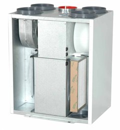
Flexit SL4 R air handling unit (image from Flexit.com)

However, in order to make this unit efficiently eliminate excess moisture from the bathroom when e.g., taking a shower, I need to adjust the fan speed to its maximum before going into the shower. Since there is some manual labor involved in pushing the button, it is often forgotten, and hence, the bathroom is not proper ventilated.

The obvious solution to this problem would be to control the air handling unit with a humidity sensor placed in the bathroom. There are two problems with this approach: 
  1. Setting the thresholds for increasing and lowering the fan speed is very difficult since the relative humidity can vary a lot during the year. I.e., when it is very moist, the fan might stay on continuously without being able to reduce the humidity in the bathroom.
  2. The optimal place for the sensor would be in the roof, which is very visible.

A temperature-based approach


So I thought, what is the root cause of humidity in the bathroom?: Well, it is hot water. Hence, I did a test by measuring the temperature of the hot water going through the pipes into the bathroom while taking a shower. At the same time, I also measured the humidity in the bathroom.


Humidity (in %)  in the bathroom and water pipe temperature (in C) while taking a shower (the shower lasted from minute 5-15 in the figure)


Not surprisingly, there is a correlation between the temperature of the water into the bathroom and the humidity in the bathroom. The next step is to construct a device that measures the temperature and communicates with the Flexit air handling unit. This will let the Flexit unit increase the fan speed whenever a hot shower is taking place.

Temperature sensor on the hot water pipe

The Arduino-build


Since I wanted a solution with no visible cables or boxes, I decides to go wireless. Luckily, my local DIY-shop (Clas Ohlson), has a wireless 433Mhz temperature sensor (36-1797) which costs close to nothing.

ESIC Temperature sensor from Clas Ohlson


In addition I bought a 433Mhz receiver from Deal Extreme. It is a peculiar unit since it has a lot of pins I do not understand whats for and as typical for Deal Extreme is does not ship with any sort of documentation. Nevertheless, all I needed was VCC, GND and DATA. The latter connection does not come with a soldered pin and I really do not know why. (Typical Deal Extreme confusion). However, it is straightforward to see that the receiver and the data-pin works by connecting it to a scope.

Based on this guide (which is again based on this guide) it was easy to receive sensible information from the temperature sensor via 433Mhz on the Arduino

I decided to use a Arduino Nano (ehrmm... clone) on this build. The Nano from Deal Extreme does not come with a bootloader (so it can hardly be called an Arduino at all). I managed to bootload the Nano from an Arduino Mega using this guide from sysexit. Thank you for that.

433Mhz Flexit Fan control using an Arduino Nano

Back to my build. Once sorting out the protocol for the temperature sensor it is actually a super simple build. The Flexit air handling unit sets the fan speed to the maximum value when Pin 14 and 16 on J5 are connected. The purpose of this is to let e.g., a kitchen cooker hood or a C02 sensor control the fan in a simple way.

I used an 5V Omron relay to connect these two pins. An opto-isolator would have been more suitable since there is no current going, but I did not have any opto-isolator laying around the day I decided to build this circuit. You know how it is. A digital pin on the Arduino drives the relay via a 2N2222 transistor.


In addition I added a LED and a test button. The circuit is so simple that you can probably figure it out from the above picture.

The verdict


So how does the system work in practical life?

Flexit SL4 R, with wireless connection. Notice the iPhone 5V charger powering the Arduino

The system has been running flawlessly for two weeks now. The fan speed increases whenever the shower is used and stays on for about 20 minutes. I now have far less humidity in the bathroom. The nice thing about the system is that there are no visible wires since the transmitter is installed inside a water distribution cabinet (as seen above) and the receiver is installed in the same cabinet as the ventilation system. The receiver is powered by a iPhone 5V USB charger so I do not have to think about battery changes.

Future work


  1. There is of course the possibility to measure humidity in the bathroom by using an additional wireless ESIC sensor. This requires only a couple of additional code lines on the Arduino. I might use one in the future, but for now I am satisfied by my water-pipe-temperature-based moisture exhaust system. 
  2. I have my 3D-printer placed in a small room that has exhaust ventilation via the same Flexit device. In order to reduce the amount of fumes and nano-particles in the room, I always manually set the Flexit to the maximum when the printer is running. This is a very important matter according to a recent article. It would have been nice if the fan could do this automatically whenever the printer is running. I envision a future project here, using a 433Mhz transmitter connected to the Melzi board on the printer. To be continued...