Sunday, November 10, 2019

Kjernebiter (Pine Grosbeak)

I went out in the snowy gray weather today, and luckily i found the flock of Pine Grosbeaks (Kjernebiter) which has invaded Oslo this autumn. Photos taken with my 10 year old Nikon D90 and the even older 300 mm f4. All photos at f4.


Sunday, January 14, 2018

Bluetoothifying a Tivoli PAL FM Radio

Norway became the first country to shut down national broadcast radio on FM. We have now switched to Digital Audio Broadcasting (DAB) leaving a lot of FM-radios useless.


I have a few Tivoli PAL radios with fairly good sound quality. They are also rechargeable. To increase the usefulness of the PAL, I wanted to bluetoothify it. I bought a KRC-86B Bluetooth receiver on Ebay and mounted in inside the box.

Luckily, all the module need is +5V and GND, and it delivers stereo audio. Inside the PAL, the audio amplifier circuit and the FM circuit are on two separate boards. All I had to do was to rip out the wires going to the FM module and connect them to the Bluetooth module.


The FM module is the vertically mounted board, and the main board is the horizontal board with the mini-jack connectors. The connector on the main board (white wires) on the PAL has the following pin-out (left to right) Right audio, Left Audio, GND Audio, 5V, GND.


I mounted the bluetooth module on the back of the tuning capacitor. There is plenty of room inside the radio.

The verdict: It is easy to connect the radio to a smart phone. It shows up as KRC-86B v4.0. The sound quality is fairly good. However, there is some noise to be heard. As of yet, I have not figured out the cause of the noise or how to get rid of if.

Monday, October 2, 2017

Small steps

Sometimes a project stalls for a while. A long while. You know you will get back to it. You just have to compete all the other tasks in life first. But you know that you will not quit. You will finish the project - oh yeah. All that it takes is a little discipline. And a few years.


My decatron-nixie-HF-radio is one such project. I know I will finish it. Its just going to take a while. Today I surprised myself after a hiatus of 10 months and finished a 9 V regulator for the 500 V step-up DC/DC-converter for the decatron tubes.


It was only a 10-minute build. And it was not pretty. But it was an important step towards the (one time in the future) finished project. Stay tuned. The front panel is soon to be finished.

Sunday, June 11, 2017

Hiding an ugly Wi-Fi router with some old books

Disclaimer. This post is not directly related to electronics DIY, but it is somewhat radio related. It is also DIY and a hint of crap.


I have an ugly Wi-Fi router on a shelf that I would like to hide. Although I am a radio geek, all the antennas and blinking LEDs just do not match the rest of the living room. I collected some old books on a flea market, ripped of the spines, and stapled them together to create a nice box.


Ripping of the spine is a quick process using an utility knife. I left about 5 mm of the front and back cover to be able to staple them together.


This is the inner side of the construction. For the books at each end, I left the front and back cover respectively, creating a sort of flimsy box.


The finished product on the shelf. It covers the Wi-Fi router nicely. Since the box is open at the top, ventilation is not restricted. In addition, my calculations reveal that 2.4 GHz and 5 GHz should propagate nicely through these old book spines.

Since I love books, and have a few thousand titles in my library, I took great care not to dissect any useful books in the process. Others may disagree, but I found theater history. anthropology and cultural history to be of particular use for this project.

Monday, December 26, 2016

Homebrew 40dB step attenuator

A home lab needs a step attenuator.  It helps in evaluating RF amplifiers, filters and receivers. Both the legendary EMRFD-book, the ARRL handbook, and a variety of QST-articles provides circuit examples for building a homebrew device. Most of them follow the design principles from the January 1967 edition of the 73 magazine (all editions can be found for free online).


I built my device base on the 73-magazine article, but choose 20 dB, 10 dB, 5 dB, 3 dB and 2 dB sections, giving 40 dB in total. The choice was basically based on the need for about 40 dB total, and the physical limitations in the aluminum box at hand giving room for only 5 pad sections.


Each pad is a basic 50-ohm in/out pi-network. I used slightly different values from those in the article. I used standard DPDT switches (from Tayda) and attempted to shield the sections using double sided copper clad boards.


Before presenting my own result, lets examine the results from the now fifty year old 73-article (congrats).


Using shielding, the authors (W6AIG and WA6RDZ) obtained almost flat response up to about 100 MHz for both the 3, 6, 10 and 20 dB pads. The 450 MHz results seem to be off by about 2 dB for each pad. The unshielded version (albeit the 20 dB section was shielded) is off by about 5 dB at 450 MHz. Lets look at my version, built 50 years later (with much less experience that is).


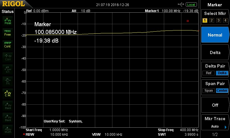
Above is the plot with all sections OFF from 1 Mhz to 400 MHz. The curve is reasonable flat, and maxes at 247 MHz with -1.47 dB.


Above is the 2 dB section over the same frecquency range. The response is close to 2 dB within the HF spectrum but -3.57dB at 247 MHz.


The 3 dB section above. Almost the same results. -5 dB at 292 MHz.


The 5 dB section. Can be defined as 5 dB within the HF spectrum but goes down to -7.43 at about 400 MHz.


The 10 dB section is better. Pretty close to 10 dB over the measured range. In fact, the 10 dB pad was fairly ok up to 1.5 GHz when used alone.


The 20 dB section is the worst. Most articles recommends no more than 20 dB attenuation per section in a step attenuator as there will be some leakage. My 20 dB section goes up to only 15 dB at 375 MHz but is still close to 20 at 100 MHz.


All sections swithed to ON. Should yield 40 dB over the range, but goes down to 30 dB at 400 MHz. This proves that the step attenuator is of little use in the entire VHF range, but could be useful up to 100 MHz. Lets look at the HF range only (1-30 MHz).


All attenuator sections is switched ON, which gives the worst results. Still, it is close t 38-39 dB over the HF range.

I am satisfied with these results since I am only going to use the device below 50 MHz. However, I am a bit disappointed that I was not able to get the same results as the authors of the fifty year 73-article. I was pretty close at 100 MHz but no cigar... My attempts to shield the 20 dB section with more copper clad boards did not give impressive results (only 0.5 dB better, at best), so those were left out in the final device. It could be that other switches could give better results. Your mileage (or attenuation) may vary.


Monday, December 19, 2016

Homebrew return loss bridge

I have had some problems making return loss measurements using my homebrew directional coupler, and decided to build the return loss bridge from EMRFD and the ARRL handbook.


This is the final device. Obviously, "IN" denotes RF input, "DUT" denotes Device Under Test, and "DET" means Detector.


The circuit (picture from the handbook) is fairly simple. I used 51 Ohm resistors and a FT 37-43 with 10 bifilar turns and BNC connectors.


 I connected the bridge to a spectrum analyzer to get a picture on the directivity.


I used my homebrew dummy load as a 50 ohm terminator.


I guess you need experience with a similar spectrum analyzer to understand the plot, but anyways, I measured a maximum return loss of 37.6 dB, which I believe is fairly good directivity for a homebrew return loss bridge. It should be noted that the dummy load is not an excellent terminator, but is ok up to about 100 MHz.


The same plot show the return loss on my shortened 20 m dipole. The SWR is at its best at 1.46 at 13.8 MHz. It seem a bit detuned as it should resonate in the low end of the 20 m band, but fixing the antenna is another project.

All in all, the return loss bridge was a fun project, and I am sure it will be a useful tool for future measurements in my little home lab.