I used two russian OG-4 tubes. I prefer the orange look of the neon tubes rather than the purple look of the argon filled OG-3 tubes. The latter tubes just look to modern for my liking. On the above picture you can see how I have mounted the tubes on a rig alongside two Magic eye tubes.
The schematics is more or less directly from the Threeneurons page. It uses two output pins from the arduino, and one input-pin. My high voltage supply is somewhat unstable, so I used a zener diode to protect the input pin from over voltage.
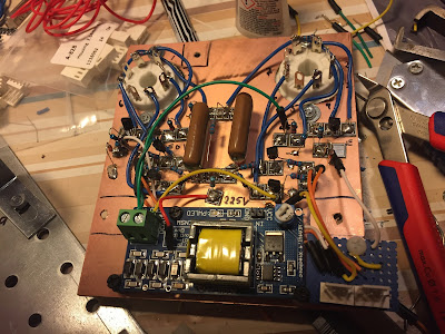
The above picture show the PCB, soldered Manhattan style. The high voltage power supply is from Ebay, and works best with less than 10V on the input side, but can provide up to 1000V. The current is however in the microampere area, hardly enough to kill a mosquito, and just enough to drive two dekatrons at 450 V. There is also some other outputs on the board providing around 170 and 250 V respectively.
I am going to use the dekatrons as part of the display solution for my homebrew RF transceiver. Now I have the Nixie display, magic eyes and the dekatrons under control (the radio itself is not finished yet). Even my cardboard mock-up is looking great!
The above video show the prototype assembly.
The dekatron code is as simple as this. Notice that the input pin is not used in the below code.
int DekOut11=12;
int DekOut12=11;
int DekIn2=6;
int DekOut21=5;
int DekOut22=4;
int count=0;
void setup()
{
pinMode(DekOut11, OUTPUT); // sets the digital pin as output
pinMode(DekOut12, OUTPUT); // sets the digital pin as output
pinMode(DekOut21, OUTPUT); // sets the digital pin as output
pinMode(DekOut22, OUTPUT); // sets the digital pin as output
}
void loop()
{
if(count<30)
{
digitalWrite(DekOut11, HIGH);
delay(10);
digitalWrite(DekOut21, HIGH);
delay(50);
digitalWrite(DekOut12, HIGH);
digitalWrite(DekOut22, HIGH);
delay(10);
digitalWrite(DekOut11, LOW);
digitalWrite(DekOut21, LOW);
delay(10);
digitalWrite(DekOut12, LOW);
digitalWrite(DekOut22, LOW);
delay(10);
count++;
}
else if(count>=30 && count < 60)
{
digitalWrite(DekOut12, HIGH);
digitalWrite(DekOut21, HIGH);
delay(10);
digitalWrite(DekOut11, HIGH);
digitalWrite(DekOut22, HIGH);
delay(5);
digitalWrite(DekOut12, LOW);
digitalWrite(DekOut21, LOW);
delay(5);
digitalWrite(DekOut11, LOW);
digitalWrite(DekOut22, LOW);
delay(5);
count++;
}
else
count=0;
}


Neat stuff! Love to see the old high-voltage eye candy interfacing with modern hardware. I enjoyed your post on the WA2ABY amp, and am looking forward to how you get on with the Minima!
ReplyDeleteCheers, de KK9JEF
*WA2EBY that is. Oops!
Delete