Monday, December 26, 2016

Homebrew 40dB step attenuator

A home lab needs a step attenuator.  It helps in evaluating RF amplifiers, filters and receivers. Both the legendary EMRFD-book, the ARRL handbook, and a variety of QST-articles provides circuit examples for building a homebrew device. Most of them follow the design principles from the January 1967 edition of the 73 magazine (all editions can be found for free online).


I built my device base on the 73-magazine article, but choose 20 dB, 10 dB, 5 dB, 3 dB and 2 dB sections, giving 40 dB in total. The choice was basically based on the need for about 40 dB total, and the physical limitations in the aluminum box at hand giving room for only 5 pad sections.


Each pad is a basic 50-ohm in/out pi-network. I used slightly different values from those in the article. I used standard DPDT switches (from Tayda) and attempted to shield the sections using double sided copper clad boards.


Before presenting my own result, lets examine the results from the now fifty year old 73-article (congrats).


Using shielding, the authors (W6AIG and WA6RDZ) obtained almost flat response up to about 100 MHz for both the 3, 6, 10 and 20 dB pads. The 450 MHz results seem to be off by about 2 dB for each pad. The unshielded version (albeit the 20 dB section was shielded) is off by about 5 dB at 450 MHz. Lets look at my version, built 50 years later (with much less experience that is).


Above is the plot with all sections OFF from 1 Mhz to 400 MHz. The curve is reasonable flat, and maxes at 247 MHz with -1.47 dB.


Above is the 2 dB section over the same frecquency range. The response is close to 2 dB within the HF spectrum but -3.57dB at 247 MHz.


The 3 dB section above. Almost the same results. -5 dB at 292 MHz.


The 5 dB section. Can be defined as 5 dB within the HF spectrum but goes down to -7.43 at about 400 MHz.


The 10 dB section is better. Pretty close to 10 dB over the measured range. In fact, the 10 dB pad was fairly ok up to 1.5 GHz when used alone.


The 20 dB section is the worst. Most articles recommends no more than 20 dB attenuation per section in a step attenuator as there will be some leakage. My 20 dB section goes up to only 15 dB at 375 MHz but is still close to 20 at 100 MHz.


All sections swithed to ON. Should yield 40 dB over the range, but goes down to 30 dB at 400 MHz. This proves that the step attenuator is of little use in the entire VHF range, but could be useful up to 100 MHz. Lets look at the HF range only (1-30 MHz).


All attenuator sections is switched ON, which gives the worst results. Still, it is close t 38-39 dB over the HF range.

I am satisfied with these results since I am only going to use the device below 50 MHz. However, I am a bit disappointed that I was not able to get the same results as the authors of the fifty year 73-article. I was pretty close at 100 MHz but no cigar... My attempts to shield the 20 dB section with more copper clad boards did not give impressive results (only 0.5 dB better, at best), so those were left out in the final device. It could be that other switches could give better results. Your mileage (or attenuation) may vary.


Monday, December 19, 2016

Homebrew return loss bridge

I have had some problems making return loss measurements using my homebrew directional coupler, and decided to build the return loss bridge from EMRFD and the ARRL handbook.


This is the final device. Obviously, "IN" denotes RF input, "DUT" denotes Device Under Test, and "DET" means Detector.


The circuit (picture from the handbook) is fairly simple. I used 51 Ohm resistors and a FT 37-43 with 10 bifilar turns and BNC connectors.


 I connected the bridge to a spectrum analyzer to get a picture on the directivity.


I used my homebrew dummy load as a 50 ohm terminator.


I guess you need experience with a similar spectrum analyzer to understand the plot, but anyways, I measured a maximum return loss of 37.6 dB, which I believe is fairly good directivity for a homebrew return loss bridge. It should be noted that the dummy load is not an excellent terminator, but is ok up to about 100 MHz.


The same plot show the return loss on my shortened 20 m dipole. The SWR is at its best at 1.46 at 13.8 MHz. It seem a bit detuned as it should resonate in the low end of the 20 m band, but fixing the antenna is another project.

All in all, the return loss bridge was a fun project, and I am sure it will be a useful tool for future measurements in my little home lab.


Sunday, August 14, 2016

Dekatron tubes controlled by arduino

Interfacing dekatron tubes with a microcontroller is fairly easy, once you understand how the tubes work. Threeneuron's Pile o'Poo of Obsolete Crap provides the necessary background information and schematics for making this work.


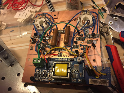
I used two russian OG-4 tubes. I prefer the orange look of the neon tubes rather than the purple look of the argon filled OG-3 tubes. The latter tubes just look to modern for my liking. On the above picture you can see how I have mounted the tubes on a rig alongside two Magic eye tubes.


The schematics is more or less directly from the Threeneurons page. It uses two output pins from the arduino, and one input-pin. My high voltage supply is somewhat unstable, so I used a zener diode to protect the input pin from over voltage.


The above picture show the PCB, soldered Manhattan style. The high voltage power supply is from Ebay, and works best with less than 10V on the input side, but can provide up to 1000V. The current is however in the microampere area, hardly enough to kill a mosquito, and just enough to drive two dekatrons at 450 V. There is also some other outputs on the board providing around 170 and 250 V respectively.


I am going to use the dekatrons as part of the display solution for my homebrew RF transceiver. Now I have the Nixie display, magic eyes and the dekatrons under control (the radio itself is not finished yet). Even my cardboard mock-up is looking great!


The above video show the prototype assembly.

The dekatron code is as simple as this. Notice that the input pin is not used in the below code.

int DekIn1=13;
int DekOut11=12;
int DekOut12=11;
int DekIn2=6;
int DekOut21=5;
int DekOut22=4;

int count=0;

void setup()
{
  pinMode(DekOut11, OUTPUT);      // sets the digital pin as output
  pinMode(DekOut12, OUTPUT);      // sets the digital pin as output
  pinMode(DekOut21, OUTPUT);      // sets the digital pin as output
  pinMode(DekOut22, OUTPUT);      // sets the digital pin as output
}

void loop()
{
  if(count<30)
  {
    digitalWrite(DekOut11, HIGH);
    delay(10);   
    digitalWrite(DekOut21, HIGH);
    delay(50);                 
    digitalWrite(DekOut12, HIGH);   
    digitalWrite(DekOut22, HIGH);
    delay(10);  
    digitalWrite(DekOut11, LOW);  
    digitalWrite(DekOut21, LOW); 
    delay(10);  
    digitalWrite(DekOut12, LOW); 
    digitalWrite(DekOut22, LOW); 
    delay(10);
    count++;
  }
  else if(count>=30 && count < 60)
  {
    digitalWrite(DekOut12, HIGH);
    digitalWrite(DekOut21, HIGH);     
    delay(10);                 
    digitalWrite(DekOut11, HIGH); 
    digitalWrite(DekOut22, HIGH);    
    delay(5);  
    digitalWrite(DekOut12, LOW); 
    digitalWrite(DekOut21, LOW);       
    delay(5);  
    digitalWrite(DekOut11, LOW); 
    digitalWrite(DekOut22, LOW);  
    delay(5);
    count++;
  }
  else
    count=0;
  
  
}

Thursday, July 21, 2016

Magic Eye Tube 6e5c

Magic Eye Tubes were used as RF-indicator tubes on radios from the 1930s until the end of the tube era and needle movement meters displaced them.


I love the glow of these tubes and want to use one as a rudimentary S-meter in my homebrew HF-transceiver. I purchased two Soviet 6e5c tubes from Ebay. I think both of them were used. I also bought two VU-meter PCBs from a Hong-Kong Ebay seller.


I could not find a schematic, but drew the circuit diagram based on the PCB on a piece of paper in order to understand the circuit. From my understanding it is a basic buffer audio amplifier followed by a DC coupled stage that rectifies the negative half cycle to provide the negative DC to drive the Magic Eye Tube.


Soldering the PCB was simple and I had all components in my junk box. The tube is mounted in a 8 pin PCB-mounted socket. There seems to be room for a LED beneath the tube. Nice if you want to pimp it up a notch or two. I do not want such modern nonsens in my old-school experiments, so I skipped that.


For the power supply I purchased a high-voltage supply from Ebay. Unfortunately, it does not seem to be able to provide enough current to drive the tube at any higher voltage than 180V, so it is a bit dim. I have to find an alternative solution. For the heater I used 6.3 V DC.


I used a signal generator to test the circuit. It was very satisfying to see the Magic Eye Tube perform its magic. The above video should convince you.


Future work include soldering up another tube and mounting them in a box together with my Nixie-tube display and some hefty dekatrons.

Saturday, June 18, 2016

WA2EBY IRF510 amplifier

The WA2EBY amplifier is a famous linear amplifier project published in QST in March and April 1999 by Mike Kossor WA2EBY. As this amplifier can give up to 50W out with 1W drive, it is a perfect pair for my Softrock RXTX amplifier.


The articles can be found on the ARRL-site (search for WA2EBY) and are highly recommended reading.

I have had a suitable box laying around for quite some time that was perfect for the amplifier project. I decided to go for Manhattan style construction using mainly the parts I already had in my junk-box and not order the PCBs and toroid set which are available from different sources on Ebay. In other words: a low-cost project.


The first I did was to make room for the IRF510 mosfets and two heat sinks. I drilled the holes in the aluminum box with a hole saw.


Then I made the RF-detector part (used for RX/TX) switching. It is in the upper part of the picture between the two relays.


I followed the articles and the schematics as best I could. The only alteration I did was to use 12V relays (instead of 15V) and a 7812 regulator for the relays and a 7805 regulator for the MOSFET bias instead of zener diodes. The above picture shows the power supply part. It is a rather conventional design. I addeda heat sink on the 7812 to make it handle 28V without dying on me.


I used a 1dB pad on the input (can be seen to the right of the left relay). It is probably not necessary to use a pad but it might improve the stability and provide a solid 50 Ω load for the Softrock RXTX Ensemble.


Mike Kossor recommends using teflon wire in output transformer due to the possible high temperature. I did not have that and used standard stranded wire which will probably survive just fine. I used coax cable for interconnections to and from the IRF510s.


I used 5k potmeters for the bias adjustment. The value should not be critical since it only acts as a voltate divider. The article does not specify the bias current, and different sources on the Internet recommend between 10mA and 100mA. I decided to try 60mA and used the method described in W2AEWs excellent video.


I only made one of the many low pass filters in the schematic (for the 17m/20m bands) following the instructions from WA2EBY. There is no band-switching at the moment, but there should be plenty of room for that later.


The network analyzer plot shows that the filter is far from excellent. The -3dB point is as high as 20 MHz and the 2nd harmonic frequency for 20m transmissions is only about -23dB down. It does not mean that the filter is useless, but I will change it later to a steeper filter and lower the -3dB point when I`m at it. Nevertheless, the output waveform seems nice, and an FFT analysis show that the 2nd harmonic is within legal limits.


A picture of the final assembled amplifier. The switch on the front panel is on/off. One LED indicates ON, whereas the other indicates TX.


The rear of the amplifier. I used banana jacks since I like them, they are robust and cheap. A protective diode takes care of business should I ever connect red to black.

The verdict


Using a signal generator and a dummy load, the amplifier easily produces about 30 W on 1W input. The amplifier seems very stable, and I have had no problems what so ever. The power consumption and efficiency is about the same as WA2EBYs figures.


The above picture show the unit with an MFJ antenna tuner for size comparison. A nice pair. With my Softrock I usually drive the amplifier to about 10-15 Watts on 20V and this have given me many contacts on JT65/9.  I live in an antenna restricted environment, and have struggled hard to get out with my mere 1W from the Softrock. I believe that this amplifier will give me lots of joy in the future.

Further reading


Thursday, May 5, 2016

EMRFD Direct conversion 40m receiver in a tea caddy

I woke up one day eager to build something simple (at least I thought is was simple) and opened up the first chapter in EMRFD and decided to build the 40m direct conversion receiver. I already had most of the components in my junk box. By the way, Experimental Method in RF Design (EMRFD) is the best book about homebrewing amateur radio gear. You should get it if you don`t have it.

I know you are sitting on the edge of your chair, eager to see the end result, so I will give it to you straight away.  Here it is: My 40m Direct Conversion Tea Caddy Receiver.


Then, lets rewind back to the build process. I started off with the schematics from EMRFD.

The first chapter of EMRFD is available online, so I guess I will not go to jail by showing the circuit diagram here. 
The receiver is based on a NE602 gilbert cell mixer and the famous and old LM386 audio amplifier. The rest of the components are a few capacitors, including three tunable, two T37-6 toroids, and some resistors. 


Prototype of the mixer circuit almost done.


Prototype of the receiver is now finished. In the first version I followed the circuit diagram from EMRFD 100% and used two 75pF air tuning caps (from Russia). The receiver was very difficult to tune with those caps, and I got some oscillations. It was a very fine Theremin, however.


The above video show the performance of the receiver. It is not very sensitive, but it is working. In this version I had some problems with the preselector filter. It seemed like all the RF went straight to ground. Trying to debug this problem did not help much, so in the above video, the antenna is connected straight to the NE602.


For the second version I used just one tuning capacitor of 80pF. It was even more difficult to tune, but I got rid of the oscillations. In addition, I went ahead and used a different preselector circuit from QRPme.com Sudden receiver.


On the final version, I used a 60pF polyvaricon with a reduction drive as the tuning cap and adjusted the oscillator circuit to enable the receiver to tune from 6.9-7.3MHz. It was build using Qrpme MePads in sort of Manhattan style. I soldered the component on two PCB boards which was soldered together to fit in a oriental Chinese tea caddy.


Finally, I added a switch and a 5mm LED. The receiver is powered by 6xAA batteries. It could probably run on anything between 6-9 volts. In the datasheet of the NE602, it says that the maximum supply voltage is 9V, so I am probably pushing it a bit. I used a protective diode and a series resistor for safety reasons and to keep the voltage down a bit.


I used an SMA-connector on the back.


The final receiver. Eager to sniff RF from the ether...


The schematics for the receiver (using Fieldnotes schematics software). The series diode is not in the schematics, but I put it in for good measures. I used somewhat different component values in the colpitts oscillator than those in EMRFD.

The verdict

It was a very fun build. It is a simple circuit on the paper, but it sure teaches you a lot regarding radio functionality. Alright, the receiver works, but it does not seem very sensitive. I should be noted, firstly: that I do not have any 40m capable receiver to compare with. Secondly, my antenna is not very good on 40m. Thirdly, I have no idea what I am doing.


That being said: CW pops in very nicely, while SSB is a bit difficult to tune in. The oscillator seem suprisingly stable given that it is a VFO rather than a VXO, and the fact that I used random capacitors and no fancy NP0-ones. At least it was stable enough to receive RTTY with fldigi during a brief experiment.

In a future version I would like to add some sort of audio filtering before the LM386. Some sort of audio gain control would also be nice, since it is a bit loud on my iPhone headphones on strong signals. 

Further reading: