I bought about 50 HC-49 24MHz crystals from different ebay sources and started out making the G3UUR colpitts oscillator tester from Experimental Methods of RF Design (EMRFD). I used 330pF capacitors for Cf (Ref EMRFD) and measured Cs to 35pF (including the switch).


All crystals were fundamental mode crystals, but they were all over the place frequency-wise. I borrowed an old Phillips PM6671 frequency counter for the characterization, as my own counter does not go all the way to 1Hz resolution.

I used boxes with small compartments to keep the crystals in order during the work.

The frequencies was jotted down in Google Sheets (with the G3UUR switch in both positions), and then I sorted the crystals by frequency.

I found seven crystals within 65 Hz for the QER crystal filter. I calculated Cm for the crystals using the updated formula from the 2015 ARRL handbook, and used Dishal to calculate the crystal parameters.

A 2.8 kHz bandpass resulted in 234pF capacitors and input/output impedances of 22.6 Ohms. I did not use this alternative, however. Instead I constructed the filter for 50 Ohm in/out, which required 109pF (I used 100pF) and an estimated bandwidth of 5.6 kHz. Probably a bit wide, but I wanted to give it a try.

Then I "characterized" a few capacitors and soldered the filter together bravely. In the above picture you see a 6dB pad at the input and a 51 ohm resistor at the output. I have no network analyzer so I had to improvise.


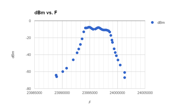
I used a Si5351 controlled from an Arduino. A few buttons let me step the frequency in 100Hz intervals. The Si5351 was connected to the input of the filter and the output was connected to an oscilloscope. For every 100Hz interval, I jotted down the RMS voltage at the input and output, and calculated the loss.
Anyway, the filter is good enough for initial testing, and I am satisfied. I think I need a simple Scalar Network Analyzer, however, as all these measurements were a bit tedious, and it could be interesting to do them again them with different capacitor values.
No comments:
Post a Comment